A hybrid rocket engine uses both liquid and solid propellant, taking advantage of both methods - possibility to control the burn time and maintain relatively simple combustion chamber design. One major drawback of the hybrid engines is the low regression rate, which relates to the thrust level that can be achieved. There are different ways how to increase the regressions rate such as changing the solid fuel grain, changing the surface structure and geometry of the grain, stacking the grain, etc. But even these methods have their own drawbacks that affect the regression rate. Changing the surface structure and geometry requires additional manufacturing effort, but it allows to improve the regression rate by improved gas-flow shape while maintaining the material properties. One common way to achieve more complex surface geometries is to use a soluble mold and liquid propellant that is cured to a solid state. In this paper the authors investigated 3D-ptined, flow-optimized, soluble mold for rocket engine propellant. Hydroxyl-terminated polybutadiene (HTPB) was chosen as the fuel and N2O was chosen as the oxidizer. Polyvinyl alcohol (PVA) was chosen as the mold material which can be dissolved in water. Special test bed was developed to perform tests on the obtained fuel grain.
Three different mold shapes was discussed in the paper:
- Cylinder shape mold - The most simplest one, but this also has the worst regression rate. This shape will result in a fuel grain with a low thrust and long burn time.
- Star shape mold - This mold has higher surface area compared to the cylinder shape; thus the final surface area of the fuel grain that will come in contact with the oxidizer will also increase and lead to increased regression rate and increased thrust. This is a common choice for solid fuel engines.
- Flow-optimized twisted star shape mold - This shape was proposed by the authors and it has the same star shape cross section as the previously described mold, but in this case, the star is twisted 360 degrees helically along the central axis. The resulting mold and fuel grain can be seen in figures 1 and and 2., respectively.
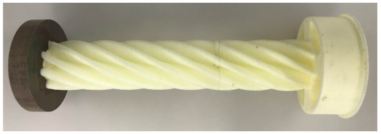
Figure 1. The two moldings are glued together (white-yellowish) and onto the vortex disk (dark brown)
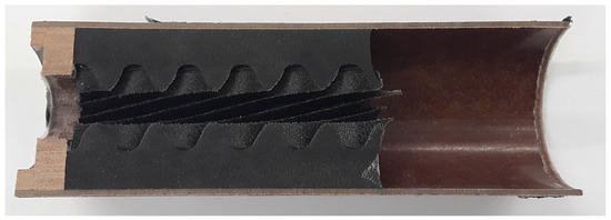
Figure 2. Sectional view of a test fuel block after the mold was dissolved.